An Introduction to
USB
Moving Automation Data Over USB
USB is a mainstream method for connecting many commercial devices but like Ethernet before it, it is slowly being adopted for broad use on the factory floor.
Ethernet today is pervasive on the factory floor but it wasn’t always so. In fact, it had a hard time finding a home there. For many years, engineers complained about its real time capability, connector reliability, ability of Ethernet hardware to survive under harsh conditions, and other issues. Ethernet overcame those concerns and now is the most important automation network on the factory floor. Proponents of USB on the factory floor point to the Ethernet example to claim that USB can also overcome that kind of skepticism. With the explosive growth of USB in the office environment, a reported several billion devices, advocates are hoping that history repeats itself.
It’s hard to believe that will happen. USB is not Ethernet. On many different levels. It’s clear that it’s one of the fastest growing PC technologies and that it is the standard bus for PC peripherals because it offers ease-of-use, high throughput and universal acceptance on the PC platform. But that doesn’t mean it will be adopted as a prime technology for factory floor automation. Instead it will most likely find a home as a niche technology in a few specialized applications.
This article examines USB and it’s applicability for factory floor applications. It addresses the history of USB, the technology, the advantages and limitations of USB in the factory floor environment and how USB will most likely be deployed in the coming years.
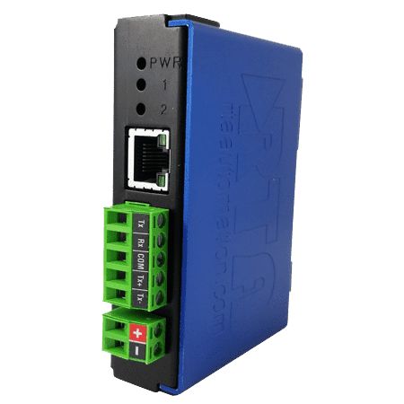
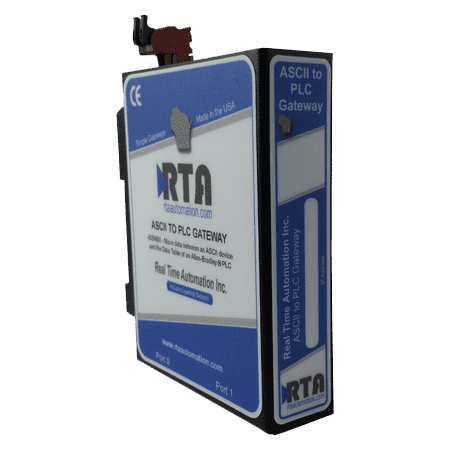
Featured USB Gateways
Background
USB is a technology of the 1990s. 1996 to be exact. PCs were really hitting the mass market in the 1990s and there was a new peripheral every day. It seemed that every minute there as a new printer, camera, pointing device, media player, network adapter, external hard drive and more being introduced.
Delivering and managing the drivers for all these devices got to be a pain very quickly, but the immediate problem was that users quickly ran out of serial and parallel ports. It wasn’t such a big deal for the tower PCs that you kept under your desk. The manufacturers of those guys delivered them with scads of serial ports and parallel ports.
The real problem was the laptop wars. The battle in that market was over cost and size. Serial and parallel ports lost on both counts. They were expensive metal components that took up a lot of space. It was clear that a replacement had to be found.
Enter USB (Universal Serial Bus) and fast forward just eight years later to 2004. 1 billion USB devices in the world. And estimates for 2015 are up to 10 billion. USB brings a lot to the table over serial and parallel ports. It’s low cost, hot-pluggable, uses a Plug and Play interface, and its support for lots of devices (127) with a feature list that explains the 10 billion device estimate:

- Easy connections with no screw terminals
- Standardized connectors
Connectors that can’t be mistakenly plugged in the wrong receptacles - A Host device interface that can support devices with various levels of performance
- Hot-Swappable device connections
- Expandability when you need to add another device
- Power on the bus to support devices that can exist without a separate power connection
- Low cost implementation for device vendors. Many embedded processors contain the USB Host and/or Device implementation
On the PC side, USB is extremely elegant. It doesn’t use IRQ (Interrupt Requests), DMA channels or I/O Address space – system resources that are sometimes in short supply.
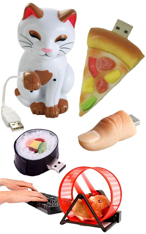
USB is now so pervasive, the nodes are now impossible to count and include wacky things like the “Thumb” drive, the USB Kitty (purrs as you work) and the USB rodent (runs at the speed of your typing).
We all use USB devices but how do they work? One of the goals of the technology was to make it easy for inexperienced users to “plug n play”.
They succeeded. You can pretty much grab most things, plug them in, wait for that little bit of magic to happen and, bang, your device is connected. You can access your pictures, external hard drive data or even watch that rodent run as you type.
But what is that “magic” and what implications does it have for the factory floor?
Technology Overview (The Magic)
You’re probably already familiar with architecture of USB. There is a root hub, usually in your laptop that is the center of the tiered-star architecture. The network is tiered through hubs which can extend the tree-like structure for five levels. Up to 127 devices can be connected into the tree.
Understanding the USB technology gets difficult because of the complexities introduced by each successive revision. USB 1.0 had the most basic capabilities with the most recent revision, 3.0, adding a 5 Gbit/s super speed and Full Duplex operation.
USB Revisions
Here’s a quick overview of each revision:
USB 1.0 (Released January 1996)
- Two Speeds, 1.5Mbit/s (low bandwidth) and 12Mbit/s (full bandwidth)
- Basic Device Class Implementations
USB 2.0 (Released April 2000)
- Added the “Hi-speed” maximum signaling rate of 480 Mbit/s
- Introduced the mini connectors
- Enhanced the electrical interface
- Added a battery charging specification for people who wanted to use their USB Port as a charging station
- Added On-The-Go, meaning that one USB device could talk directly to another USB device without using that root hub
USB 3.0 (Released November 2008)
- Added 5Gbit/s data transfer rate (Super-speed)
- Decreased Power Consumption
- Device initiated communications (In 1.0 and 2.0 a device could only communicate when spoken to by the host)
So, why haven’t you heard more about 3.0? It rolled out almost 4 years ago and today, there are few 3.0 devices. That’s largely because of a lack of support from Microsoft and to some extent, Linux. Microsoft announced USB 3.0 support for Windows 7 but shipped it without. And only recently have Linux distributions shipped with 3.0 support. Until the OS supports it, there is little reason for device vendors to move forward with 3.0 compatible products.

USB Electrical Interface
Unless you are a true geek, you probably don’t care much about the electrical interface but you might want to know that USB operates on 5VDC power and that 100ma is the basic unit load for USB. Devices designating themselves low power devices cannot draw more than one unit load. High power devices cannot draw more than 5 unit loads (500ma). Self-powered devices, devices that are powered from an external power connection, can draw up to 1 unit load from the bus.
In USB 1.0 there were four wires; 5VDC, Common and two data lines. The data lines use differential signaling to suppress electrical noise. If this reminds you of RS485 you’re on the right track; the electrical implementation of USB 1.0 is nearly identical to RS485 implementation.
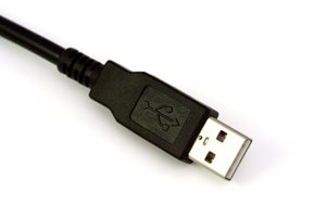
Another complexity that causes some discomfort is a proliferation of plugs for USB. In the original USB specification there is simply a standard four pin plug and receptacle. The A plug is plugged into the hub. The B plug is plugged into a device. Later Mini A and Mini B were added to the mix. These plugs besides decreasing the USB profile added a fifth wire for identification. This ID line allows the Host controller to determine if there is a device plugged into a USB port. If that’s not enough, Micro A and Micro B connectors provide another version that is widely used in cameras and cell phones.

One of the interesting side notes to the USB connector issue is that the specification clearly states that the USB icon must be embossed on the “topside” of the USB plug, to provide “easy user recognition and facilitate alignment during the mating process”. The manufacturer’s logo is recommended to be placed on the opposite side from the USB icon. Despite this clear specification, many products on the market have the USB icon on the wrong side of the plug.
USB Operation
The USB software specification runs on for volumes and describes how devices are recognized, packetize data, and detect errors. There are a few elements of the operation of USB that are interesting to someone casually interested in this technology:
ENUMERATION – Enumeration in the USB world describes the process of a new device connecting to a host. After a power cycle, a USB host queries all the devices on the USB network. Each device is assigned an address and the host identifies the type of data transfer required. As the Enumeration process proceeds, the USB host tracks the total bandwidth that devices are requesting and once 90% of the bandwidth is allocated, the host denies access to other devices requesting defined bandwidth.
DEVICE CLASSES – Every USB device is defined by a class code, a number from 0 to 255. In the Windows world, the class code is what is used to identify and load a suitable driver for the USB device. These device class codes include:
01 – Speakers and Microphones
03 – Keyboard, Mouse and Joystick
06 – Scanner
07 – Printer
08 – Mass Storage devices
Devices with a particular class code must conform to the Device Class specification on the USB-IF website. That is the reason that any USB printer (Device Class Code 7) can use the same driver as every other USB printer. Devices that have special functionality use Device Class Code 255. Vendors supplying devices with that Device Class must supply the driver for the device.
DEVICE PIPES– A Pipe is a logical channel between the USB Host Controller and a functional entity in a USB Device named an Endpoint. USB hosts can have up to 32 pipes; 16 into the host and 16 out of the host. There are several different types of Pipes:
- Isochronous Transfers – Transfers at a guaranteed data rate. This kind of Pipe is used for Video and Audio; very fast but not necessarily without data loss.
- Interrupt Transfers – Devices that need instant response (your mouse uses an interrupt transfer)
- Control Transfers – Short messages that contain commands and responses
- Bulk Transfers – Large transfers of data between the host and a device. This would include File type transfers where bandwidth and latency are not guaranteed (think printers).
CONNECTION INITIATION – There is a well-defined sequence that is followed when a new device is connected to a USB port. This sequence allows the Host to identify the device speed (Lo/High/Super) and assign an address to the device. Anytime the Host is Reset, the connection process is restarted. At the end of the connection process, the USB Host can signal the OS or application program that a new device is now attached to the network with this Device Class so that the appropriate driver can be instantiated.
This is a very incomplete treatise on the USB specification. It’s a few of the highpoints as it’s impossible to compress all 650 pages of USB specifications into a short article like this. For all the relevant details visit http://www.usb.org/home.
Factory Floor Operation, Limitations and Concerns
USB is growing on the factory floor for a lot of reasons. One of the major ones is that it is hard to buy PCs with Serial Ports. And it’s hard to buy PCs with multiple card slots so that you can add serial ports. Plus the fact that USB is ubiquitous around the office makes it a convenient choice for automation applications.
It’s convenient but is it the right choice?
Advantages of USB on the Factory Floor
-
PERFORMANCE – With 480Mbit/s transfers in USB 2.0 and 5Gbit/s in USB 3.0, USB is faster than almost every industrial network except Ethernet.
-
CONVENIENCE – The trend over the last several years is to embed web pages in a device and use them for device configuration. This works well except for the difficulties configuring a laptop to access a device on a specific automation subnet. Novice users often struggle setting a laptop’s IP address to access a device on an automation subnet.
-
Users now find it difficult to accept software configuration tools and all the administrative overhead of managing lots of tools for all the devices on the factory floor. This may change with the advent of new PAD computers with USB support like the Google Pad. Managing a series of automation Apps will probably be easier than managing laptop software. And given the ease and speed of connecting to a device over USB, it is possible that Pads with USB could find themselves a place as basic configuration tools.
-
-
UBIQUITOUS DEVICE SUPPORT – With several billion USB equipped devices, there are plenty of options for automation engineers to evaluate and consider. And with the ease of adding USB to their products (many embedded processors now have USB support by default) it is likely that many automation devices will have USB in the future.
-
WIRELESS USB – Available for a number of years now, wireless USB could be exactly what machine builders want. Faster than Ethernet, less costly than wired and other non-wired solutions and with higher performance than 802.11, wireless USB could become a great I/O solution for machine builders.
Limitations to USB on the Factory Floor
Now let’s look at some of the factors which might limit the deployment of USB on the factory floor.
-
TOPOLOGY CONSTRAINTS – USB 2.0 (480Mbit/s) is limited to 5 meters. That’s pretty short by industrial standards.
-
LACK OF DEVICE CLASS DRIVERS – As noted earlier, every USB device has a device class indicator. That indicator, among other things, is a prime driver of how the Operating System (Windows or Linux) identifies a driver for the device. In the PC world, there are few hard disk storage and ram limitations. Drivers for many if not all USB Device Classes can be available even if many of those drivers are never used.
-
In the automation world, outside of PC Servers, this is much more difficult. A PLC that supports USB has limited storage and can’t support all of the defined drivers. It must instead just support a much smaller number of USB devices that can be integrated into its operation. Integrating the data for a USB device into the operation of a factory floor device like the PLC is very challenging. Simple devices are much more feasible than complex devices. Limiting the Device Classes supported makes a lot of sense in this environment. A barcode reader (Device Class 3) might be the only Device that the PLC would support. The data is simple and it could tie the barcode data to a specific Tag that would get the barcode when available. Complex devices like mass storage, cameras and such would, of course, not be supported.
-
A number of PLC manufacturers are currently replacing their serial ports with USB. It appears that this is not to allow data transfer through the USB port but to allow laptop driven programming tools lacking serial ports the ability to program the PLCs over those ports.
-
-
SECURITY – Nothing can be written anymore about factory floor automation without mentioning security. USB is one of the easiest ways that a hacker can gain entry to an automation system. Those USB flash drives you pick up at that conference are great ways to bring viruses and malware into your automation system.
-
Is that true for an embedded automation system (PLCs and other devices) as well? Possibly. If you have a PLC that allows programs to be loaded from a USB stick that’s an obvious security hole. But what about protecting your data? Can your system be easily commanded to offload critical data to a USB stick? What happens if someone unauthorized gets that data?
-
-
SAFETY ISSUES – One of the more important considerations for factory floor device implementation is to make sure that devices are electrically protected. The factory floor is a nightmarish environment compared to an office environment.
-
Lots of electrical disturbances happen on the factory floor. There are huge motors starting and stopping. There are sometimes power fluctuations that can ripple through communication lines. Or with the amount of ongoing maintenance, somebody can simply mis-wire something. Unlike the office environment a lot of the signals on the factory floor are terminated by connecting bare wires to screw terminals, not prewired connectors.
-
Most factory floor devices use a form of isolation to prevent an electrical signal from propagating through a system. Ethernet has a kind of magnetic isolation between nodes. Many other devices use optical isolation.
-
USB has no isolation. Any wayward signal received by a USB device can propagate to the host and if the signal is strong enough, destroy electronics in the host and possibly in other devices.
-
Final Thoughts
It is easy to assume that USB is USB – everything just connects. USB on the factory floor is going to be much more limited. The operational issues of supporting the USB device drivers, the cable length limitations, security issues and the lack of electrical isolation all seem to doom the widespread use of USB on the factory floor. Even PC servers may be limited. It is not uncommon for IT departments to disable USB ports on factory floor servers to prevent access by unauthorized USB memory devices. USB may find a home on the automation floor to support PLC logic development tools and device configuration but the limitations are much too severe to make it a widely used technology.


